Monthly Archives: June 2013

On the emission of light

There are many circumstances in which a system will emit light.

During incandescence objects emit light because of their temperature. Everything above absolute zero emits electromagnetic radiation due to its temperature as the electrons in the object vibrate back and forth due to the motion of the atoms that make up the object. The type and amount of EM radiation emitted depends on the temperature – this is how infrared thermometers work, by measuring the intensity and wavelength of the IR radiation emitted.

incandescence

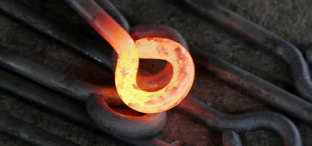
A red-hot piece of metal demonstrating incandescence.

Luminescence is the emission of light not due to temperature, and can be broken up into many sub-processes, listed below.

Fluorescence is one of the most familiar of these processes. An object fluoresces when it absorbs electromagnetic energy of one sort and subsequently emits another, usually longer-wavelength energy. This is how hidden “ultraviolet ink” works and why clothes sometimes “glow” under UV illumination. Fluorescence is a subset of photoluminescence, in which light emission is the result of absorption of photons, with the other photoluminescent process being phosphorescence, a much slower process than fluorescence in which the emission of photons is highly delayed. It is phosphorescence which is responsible for the light produced by glow-in-the-dark materials that are “charged” by light.

fluorescent-minerals
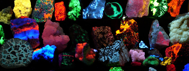
A selection of fluorescent minerals.

Phosphorescence
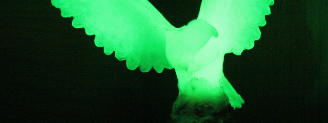
A phosphorescent statue.

Chemiluminescence is the process by which light is emitted during a chemical reaction, such as the reaction which occurs in glow sticks. Bioluminescence is a subset of this, when the process occurs in living organisms like fireflies. The other subset of chemiluminescence, electrochemiluminescence occurs when an voltage is applied to a solution; this is how LEDs operate. Cathodoluminescence is itself a subset of electroluminescence, occurring when electrons strike a material such as a phosphor, causing the electron’s energy to be converted to light. This is how old-fashioned cathode ray tube (CRT) televisions operate.

chemiluminescence
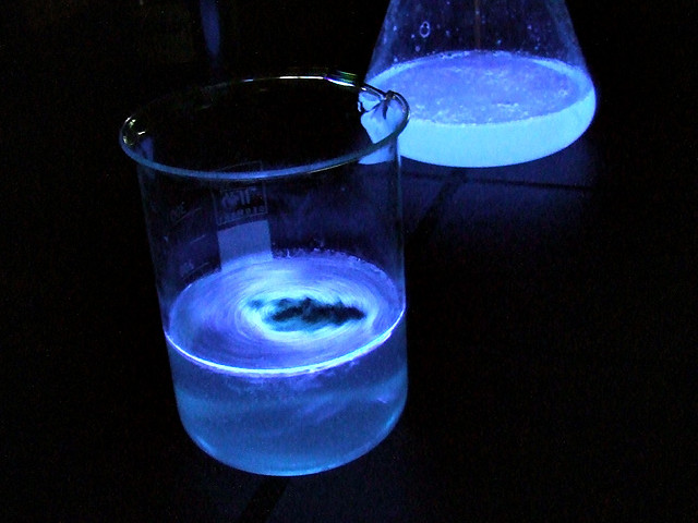
A solution of luminol demonstrating chemiluminescence.

bioluminescence-squid-firefly
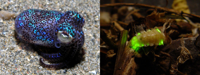
L-R: A squid and a firefly demonstrating bioluminescence.

ledsA selection of electroluminescent blue LEDs.

Crystalloluminescence is the process by which light is emitted during crystallisation and fractoluminescence when the bonds in crystals are broken.

Fractoluminescence is a subset of mechanoluminescence in which light is emitted as a result of forces acting on a solid. Other mechanoluminescent processes include triboluminescence in which the action of friction causes light to be emitted as chemical bonds in a substance are broken; piezoluminescence in which the action of pressure on a solid causes light to be emitted as electrons and holes recombine; and sonoluminescence is which bubbles in liquids excited by sound waves collapse, emitting light in the process. The exact process that causes sonoluminescence is unknown, though many suggestions including bremsstrahlung radiation, coronal discharge and proton tunnelling have been suggested.

Radioluminescence occurs when light is emitted as the result of bombardment by ionising radiation. It is radioluminescence that was previously used in glow-in-the-dark materials (in particular radium dials) and which is responsible for the glow produced by tritium illumination.

radioluminescenceA radioluminescent tritium light source.

Finally, thermoluminescence occurs when certain crystalline materials emit energy they had previously absorbed in the form of EM radiation or via bombardment of ionising radiation as a result of being heated.

Automatically removing foreign objects from photographs

Imagine that you’re on holiday, trying to photograph a famous landmark. There are sure to be other tourists around, messing up your photographs. But what if there were a way to automatically remove these interlopers from your photographs?

Here are eight photographs of the street outside a local car park, taken from the car park’s roof. In each of the photographs there is some sort of foreign object present – either a pedestrian or a car.

IMG_6524 IMG_6525 IMG_6526 IMG_6527 IMG_6528 IMG_6529 IMG_6530 IMG_6531

Below is a copy of the image, but with all of those foreign objects removed. This isn’t the result of hours of painstaking manipulation – it’s the result of running one special filter, a median layer blend, on the collection of images.

blend-resultThe median layer blend works by taking the colour values for the same pixel in each photograph and then using the median value as the value used in the output image.

For example, if the red values for the first pixel in each image were 234, 234, 197, 251, 222, 193 and 218 then the median would be 218, as it falls in the middle when they are arranged in order (193, 197, 213, 218, 222, 234, 234, 251). Because each foreign object is in a different position in each frame, the RGB values for the pixels that make them up will lie at either end of the scale, and those values will be eliminated when the median layer blend filter is applied.

It is very important that whilst taking your images that the camera remains in a fixed position; if the camera is allowed to move you end up with a blurry and oddly smooth image. The leaves in the output photograph above are slightly blurred because they were moved by the wind as the original photographs were being taken.

This technique is also very useful when taking photographs with a high ISO setting in low light. Images taken in low light are prone to noise, but because this noise is different in every image, a median layer blend filter does a very good job of removing this noise.

Here is a boring image of a London Tube network map, taken at ISO 3200 in poor light.

tube-map-original

If we look closely, the image is very noisy.

tube-map-original-closeupBut after running ten of these images through a median layer blend filter, the noise is very satisfactorily removed.

tube-map-comparison

L-R: The original noisy image and the resulting “de-noised” processed image.

I used the GIMP image processing software with the G’MIC plugin to create the images above, but I’m pretty sure similar tools are available for other packages (e.g. Photoshop).

Laser gyroscopes

A gyroscope is a device that uses the principle of the conservation of angular momentum to maintain it’s orientation. That is, when set into a motion, a gyroscope resists any attempt to alter the axis along which it is spinning.

Gyroscopes are commonly used (in combination with accelerometers) in inertial navigation systems (INSs) to detect changes in position, orientation and velocity. INSs were first developed for rockets, but have since been used in many roles, including aboard submarines, aeroplanes and spacecraft.

gyroscope-operating gyroscope-precessing

L-R: A gyroscope resists any attempt to change its orientation; and a gyroscope demonstrating precession. Note that during precession the angle of the spin axis does not change.

Most people know gyroscopes as spinning discs or wheels, as shown above, but not all gyroscopes operate in this way. For extremely high-precision uses ring laser gyroscopes (also known, in one particular form as fibre-optic gyroscopes) are used.

In a ring laser gyroscope (RLG) a beam of laser light is split, bounced off two (or more) mirrors and then these two beams are brought back together. When the two beams recombine an interference pattern is created, and by monitoring this interference pattern any change in the gyroscope’s orientation can be calculated.

A ring laser gyroscope

RLGs make use of the Sagnac effect: if the position of the mirrors changes during the time taken for the laser beam to travel around the ring, then the two beams will be out-of-phase when they recombine, and this causes the change in interference pattern that the gyroscope measures. (As a RLG does not maintain its orientation, it is not a gyroscope in the conventional sense – it is sensitive to changes in orientation due to the invariance of the speed of light rather than the conservation of angular momentum.)

RLGs are usually employed in groups of three, so as to monitor motion in three dimensions; an example of this setup is shown below.

ring-laser-ins

Because they have no moving parts, and because they are able to measure very small changes in orientation, RLGs have found many applications. They are used aboard modern fighter aircraft such as the F-22 Raptor and aboard the UGM-133 Trident II nuclear missiles used by the UK and USA.

Boomerang

The Boomerang Shooter Detection System is a gunfire locator system, designed for use against snipers, that tells its user the location of a source of gunfire, allowing those under attack to return fire. The Boomerang system can be mounted to vehicles, and works at speeds up to 60 mph, or can be used in a stationary perimeter defence role.

boomerang-mountedBoomerang mounted to an armoured vehicle.

When a bullet is fired it makes two types of noise: a muzzle blast as the round exits the barrel, and a supersonic shockwave as it moves through the air. By measuring the differences in volume and in time between these sounds reaching each of its seven microphones, Boomerang is able to calculate the range, elevation and azimuth of the shooter’s (or shooters’) position and then displays this information to its user.

This method is the one that humans use to locate sounds, though we do not have the benefit of seven ears. The algorithms that Boomerang uses are more complex than humans’, as it has to differentiate between incoming and outgoing fire, and between gunfire and other noises such as cars fireworks or cars backfiring.

boomerang-control-panel

The Boomerang display panel is shown above. Range and elevation are displayed on the green digital readout, and the azimuth is indicated on the clock display. This data is combined on the small circular LED panel in the bottom right-hand corner.

Zahavi handicaps

In 1975 biologist Amotz Zahavi proposed his handicap principle.

“It is suggested that [characteristics] which develop through mate preference confer handicaps on the selected individuals in their survival. These handicaps are of use to the selecting sex since they test the quality of the mate. The size of [characteristics] selected in this way serve as marks of quality.”

peacock-plumage

In some populations of animals some of those animals will display a costly (in terms of survival) handicap. The classic example of this is the peacock’s tail: The presence of the tail makes it more likely that the peacock will fall prey to predators; the fact that it has survived despite this handicap suggests to peahens that it possesses superior genes, and is therefore worthy of mating with.

The handicap has to be expensive (in terms of survival) in order for it to be a reliable signal as to reproductive fitness. If it is not, then all males or females could display the same signal, and the signal would serve no purpose. Other examples of Zahavi handicaps include courtship dances, the extravagant nests built by Bowerbirds and the bouncy “stotting” behaviour of gazelles.

It has been suggested that certain activities which humans engage in, such as bungee jumping or conspicuous consumption (especially of Veblen goods) are examples of Zahavi handicaps – attempts by humans to demonstrate reproductive fitness to possible mates.