Monthly Archives: December 2012

Resistor values

I am occasionally forced to teach some electronics. Looking recently at our resistor sets I was somewhat puzzled by the odd values involved.

resistor-values-E12-series

We have two sets of resistors: the E12 series and the E24 series. The E24 series has twice as many resistors for each scale (1-10, 100-1000, 1000-10000, etc.) as the E12, with the number after the ‘E’ telling you how many resistors are in the series.

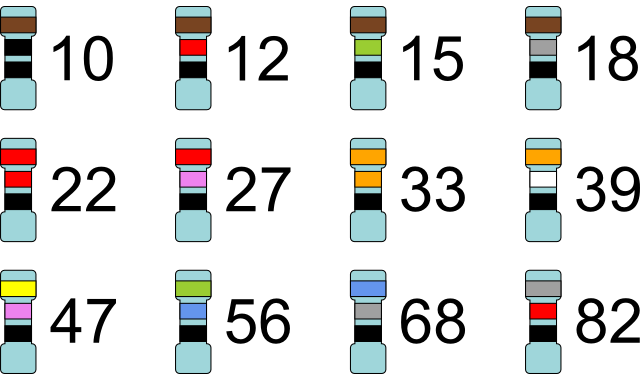
For example, in the 10-100 Ω scale the values are as follows:

E12: 10 Ω, 12 Ω, 15 Ω, 18 Ω, 22 Ω, 27 Ω, 33 Ω, 39 Ω, 47 Ω, 56 Ω, 68 Ω and 82 Ω.
E24: 10 Ω, 11 Ω, 12 Ω, 13 Ω, 15 Ω, 16 Ω, 18 Ω, 20 Ω, 22 Ω, 24 Ω, 27 Ω, 30 Ω, 33 Ω, 36 Ω, 39 Ω, 43 Ω, 47 Ω, 51 Ω, 56 Ω, 62 Ω, 68 Ω, 75 Ω, 82 Ω and 91 Ω.

The reason for the choice of values is tolerance. The resistors in the E12 scale are guaranteed to be ±20% of the stated value, so with a starting value of 100 Ω it makes little sense to produce a 110 Ω resistor as this is already within the tolerance of the 100 Ω resistor; a 120 Ω resistor will be 144 Ω at most, so it makes sense for 150 Ω to be the next value.

The resistors in the E24 scale are guaranteed to be ±10% of the stated value, therefore twice as many values are needed within the scale when compared with the E12 scale. With a starting value of 100 Ω a 105 Ω resistor is unnecessary for the same reasons described above.

For use in schools it makes sense to use E12 and E24 series resistors, as we rarely require great precision in our resistors. But for other uses it’s necessary to use more accurate resistors: the E192 series contains 192 resistors and has a tolerance of just ±0.5% and resistors with even finer tolerances are produced for super high-accuracy applications, for example in defibrillators.

Thanks to PAS for help with this post.

An unexpected hazard of manned Mars exploration

mars-surface

There are many risks associated with a manned mission to Mars. The journey itself would last between 150 and 350 days, and beside the risks associated with prolonged isolation and cramped conditions there is also the lack of real-time communication caused by the time taken for radio signals to travel the very large distances involved. Once arriving on Mars there is the presence of high levels of cosmic rays and ionising radiation to content with, all to be dealt with without proper medical facilities.

But a new paper* identifies a risk I hadn’t considered: asteroid impacts. Mars is much closer to the asteroid belt than Earth, and thus asteroid impacts are more frequent. The authors analyse the rate of crater formation on Mars and come up with a model that predicts the number of craters of a given diameter likely to be formed over a given period of time.

crater-impact-graph

Their model predicts that a one megaton (≈1 km crater) impact will occur once every 3.3 years, which would make spending any significant length of time on Mars quite hazardous. Mars’ atmosphere is much thinner than Earth’s, with an atmospheric pressure only 0.6% of ours, and so damage on the Martian surface is likely to be much more severe than for a similar impact on Earth.

* William Bruckman, Abraham Ruiz and Elio Ramos, “Earth and Mars crater size frequency distribution and impact rates: Theoretical and observational analysis”, arXiv:1212.3273.

Sonic booms and Mach cones

When an object moves through the air it pushes the air in front of it away, creating a pressure wave. This pressure wave travels away from the object at the speed of sound. If the object itself is travelling at the speed of sound then these pressure waves build up on top of each other to create a shock wave, or sonic boom.

On the left, an object travelling at Mach 0.7. On the right, an object travelling at Mach 1.0.

One of the most common misconceptions about sonic booms is that they occur only as an object accelerates beyond Mach 1.0 (through the “sound barrier”) and not during supersonic flight. This is not the case. A sonic boom is continuously created as long as an object is travelling faster than the speed of sound, and this sonic boom trails behind the object, creating a Mach cone.

mach-cone

The shape of this Mach cone depends on the speed of the object, and the faster an object is, the narrower its Mach cone. For a supersonic or hypersonic object these cones can become very narrow and thus when the sonic boom from a high-speed aircraft reaches the ground the aircraft in question has already passed by and can be quite a distance away.

The angle of the Mach cone (μ) between the shock wave and the horizontal is simple to calculate from the object’s Mach number (M).

mach-angle-equation

For an F-22 Raptor travelling at its maximum speed of Mach 1.82 the angle of the Mach cone formed is 33.3°. If the Raptor was flying at an altitude of one hundred metres then it would always be sixty-five metres away (horizontally, in the direction of travel) from where its sonic boom was detected and 120 metres in a straight line from the point of impact. At a distance of 120 metres a person on the ground is hearing (or rather, feeling) the sonic boom 350 milliseconds after it is emitted, assuming the speed of sound is 340 metres per second.

By looking at Schlieren photographs, which can image differences in gas density, we can see the shockwave created, find the Mach cone angle, and from that calculate the speed of an object moving through the gas.

bullet-mach-cone

In the photograph above the Mach cone angle is 28° and therefore the bullet must have been travelling at Mach 2.1 or 720 metres per second (assuming the speed of sound is 340 m/s).

The fission-fragment rocket

Travelling to very distant objects in space such as stars and exoplanets will require very large amounts of thrust to drive rockets to very high speeds in order that we can travel there in a reasonable amount of time. Conventional chemical rockets are unsuitable for this purpose as the thrust they provide is limited by the amount of fuel that they can carry. So far we have only travelled as far as the Moon, and that’s a mere 380 000 kilometres away.

An artist’s impression of a possible FFR design. The large grey fins are for cooling and the crew habitat or payload area is at the far end, pointing away.

The fission fragment rocket (FFR) is a theoretical engine design that uses the products of nuclear fission (“fission fragments“) to generate thrust. These fission fragments cannot normally escape from the fuel, but in an FFR this is designed to be not only possible but likely. A number of different designs have been proposed, but perhaps the most promising is the “Dusty Plasma Rocket” proposed* by Rodney Clark and Robert Sheldon.

In Clark and Sheldon’s dusty plasma rocket the fuel is a magnetically- and electrostatically-confined plasma containing tiny grains of radioactive fuel, each no more than one hundred nanometres in diameter. As the fuel fissions, the fission fragments are steered either to collection electrodes to generate electrical power, or out the back of the engine to generate thrust.

A schematic of Clark and Sheldon’s dusty plasma rocket. Fission fragments are ejected to the left to produce thrust, and on the right are collected by electrodes for electrical power. Also shown are the RF coils (red dots) used to heat the plasma and the containment field generator (orange) required to keep the dust cloud in place. The beryllium oxide or lithium hydride moderator is shown in light green.

Although the mass of the fission fragments is very small, they exit at speeds of a few percent the speed of light and are therefore able to generate a significant thrust force. An FFR “burning” one hundredth of one gram of fuel per second and ejecting those fragments at five percent of the speed of light would still be able to generate a force of 150 newtons and Clark and Sheldon calculate that their dusty plasma rocket would be able to generate a specific impulse (ISP) of 1.5 million seconds. Specific impulse is a measure of the efficiency of a rocket engine and compares the force generated with the mass of propellant used per unit time, and for comparison purposes each of the Space Shuttle Main Engines had an ISP of between 360 and 450 seconds (as ISP varies with altitude). An FFR therefore offers a huge improvement in efficiency over standard chemical rockets.

Perhaps the most interesting aspect of the fission fragment rocket is that unlike other proposed long-distance rocket designs such as matter-antimatter reactors, it is well within current technological capabilities: we could begin building an FFR tomorrow. Clark and Sheldon calculate that a ten-year mission to the Sun’s gravitational lens point, 550 astronomical units (82.2 trillion metres) from Earth would require only 180 kg of nuclear fuel and a 350 megawatt reactor, both of which are well within current design parameters.

* Rodney Clark and Robert Sheldon, “Dusty Plasma Based Fission Fragment Nuclear Reactor”, 41st AIAA/ASME/SAE/ASEE Joint Propulsion Conference & Exhibit (2005). PDF Link.